ELECTRONIC TURBINE GAS METERS TME400 VMF/VCF
TME 400 VMF/VCF (Turbine Meter Electronic) are approved for custody transfer according to
MID and offer a number of advantages over classical mechanical Turbine Meters. This includes
display of actual flow rate, data and parameter archiving and various interfaces.
METHOD OF OPERATION AND CONSTRUCTION
Introduction
The new type TME 400 turbine meters are designed for custody transfer operation with purely electronical totalizers. In contrast to mechanical turbine meters, in the TME 400 the volume flow is converted in the mechanical meter body to electrical impulses, which are transmitted to the electronical meter head where they are processed.
In this way, the TME 400 can not only display and save the totalizer reading, but also, for example, the actual flow rate. In addition, several totalizers can be realised and the meter can transmit its measured values as well as additional signals directly via various interfaces (pulses, analog, digital). Furthermore, the version TME 400-VCF offers a fully- fledged volume corrector integrated in the meter head, including pressure and temperature measurement. It calculates the standard volume besides operating flow rate and operating volume. An external volume corrector is no longer needed. For all TME 400 versions, a long-lasting backup battery ensures continued reliable operation even in the case of a complete power failure for 6+ years.
It calculates the standard volume besides operating flow rate
and operating volume. An external volume corrector is no longer
needed. For all TME 400 versions, a long-lasting backup battery
ensures continued reliable operation even in the case of a
complete power failure.
TME 400-VM
The TME 400-VM (Volume Meter) is the basic version of the TME 400 family. As the abbreviation VM indicates, it is a so-called volumeter, i.e. a pure operating volume meter for non-custody transfer applications.

TME 400-VMF
TME 400-VMF (Volume Meter Fiscal) is the name of the
turbine meter for measurement of volume under operating
conditions (custody transfer approved). It is the electronic
further development of the classical mechanical turbine
meter.
Features
• Approval acc. to MID (European Measurement Directive)
• Design acc. to EN 12261
(European Standard for Turbine gas Meters)
• Electronic totalizers
Main totalizer, additional start-stop or resettable
totalizer for low flow (or slow down) cut-off by external
signal.
• Low-torque metering system with long-term stability
Turbine design with a minimum of moving parts.
• Battery or mains operation
Autonomous operation with lithium cell for 6+ years or
external power supply and backup battery to protect
against power failures.
• Explosion protection
The TME 400 is intrinsically safe and can be used in zones
1 and 2.
• Outputs
Pulse outputs HF and LF (variable), alarm output, current
output (4-20 mA, optional).
• Flow display
• Digital interface
serial RS 485 interface for Modbus connection.
• Storage of maximum value (Qm)
• Archive
Integrated fail-safe parameter, event and measured
value archive.
• RMGViewTME
Provided software for convenient parameterization and
management of device and stored data.
TME 400-VCF
The TME 400-VCF (Volume Corrector Fiscal) combines all
features of the TME 400-VMF with the benefits of a fully
integrated custody transfer approved PTZ volume correc-
tor according to European standard EN 12405. Pressure
and temperature measurement are integrated directly into
the meter.
Additional Features (VCF)
• Volume corrector acc. to EN 12405
Integrated fully-fledged compact volume corrector
including digital pressure and temperature measurement.
• Calculation of the K coefficient
according to SGERG88, AGA8 GROSS M1 and M2 as well as
AGA NX19.
• Display
Operating volume, standard volume, current and
maximum flow can be displayed in measurement and
standard condition.
• Separate Terminal block
Inputs for pulses, pressure and temperature can be
sealed separately from the rest. The lithium battery can
be exchanged without opening the case.
ut opening the case.
INSTALLATION OPTIONS, ARCHIVES, SOFTWARE
Options for Installing the Totalizer
With the TME 400-VM the meter head can be mounted standing or lying as well as rotated about the vertical axis. For TME 400-VC the meter head is mounted standing in any case due to the pulse piping required. For both the TME 400-VM and the TME 400-VC the remote totalizer option for a separated mounting of the meter head in a distance of max. 10 m from the meter body is available.
Archives
Parameter changes, meter readings and events are stored in the archives and for the TME 400-VC additionally measured values. The memory depth is in each case: • Parameter archive (custody transfer) 300 • Parameter archive (secondary) 300 • Event archive 200 • Periodic archive 9000 • Daily archive 100 • Monthly archive 25 The measuring period can be set to 15, 30 or 60 minutes.
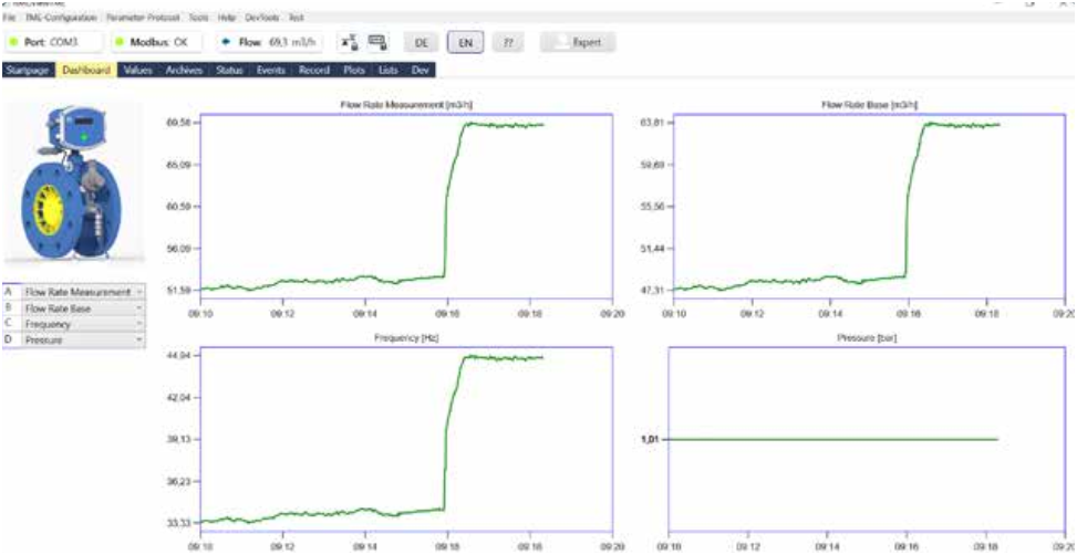
Operating software RMGView
TME The provided RMGViewTME software allows direct access to the measuring electronics with a PC. The most important functions are:

Method of Operation
With turbine gas meters the gas flow strikes a
mechanically mounted turbine wheel and drives
it. The rotational speed of the turbine wheel is
proportional to the flow rate of the gas. Since
the gas flows through an invariable cross section
(annular gap of the turbine wheel), the flow
velocity is also proportional to the volume flow.
TME 400-VMF and TME-VCF are based on the
trusted RMG Turbine Meters series TRZ03.
Dimensions and metrological performance are
identical for both.
In the TME 400, a magnetic disk is mounted on
the shaft of the turbine wheel, rotating at the
same speed as the turbine wheel. A Wiegand
sensor scans this disk and generates one electrical
pulse per revolution which is transmitted to the
electronic meter head. Each pulse is directly
proportional to a certain volume flow. The meter
can therefore display both the current flow (QM)
and the total flowed volume (VM).
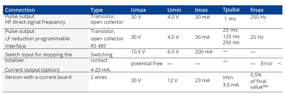
Electronic Totalizer
Possible connections for the electronic totalizer:
Furthermore, the volume corrector integrated in the TME 400-VCF allows the calculation
of the standard volume (VB). In order to do this, the meter measures operating pressure
and operating temperature in addition to the operating volume flow. From this, the
standard volume flow can be calculated using a suitable equation of state together with
the corresponding standard conditions. Then this value is summed up in the standard
volume totalizer and stored in the data logger.
and stored in the data logger.

Electronic Totalizer
Possible connections for the electronic totalizer:
PRESSURE LOSS, TECHNICAL DATA
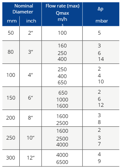
Pressure Loss
The pressure loss ∆p stated in the table applies to natu-
ral gas at Qmax and 1 bar (a). From this, the pressure loss at
measurement conditions can be calculated in accordance
with the formula below.
Pressure loss as per the formula
ρb
Qm
2
∆pm = ∆p ∙ ∙ pm ∙
0.83
Qmax
∆pm = Pressure loss at measurement conditions
(pm, Qm) in mbar
∆p = Pressure loss at Qmax with natural gas at
1 bar in mbar (see table)
ρb = Standard density of the gas in kg/m3
pm = Pressure at meas. conditions in bar(a)
Qm = Flow rate at meas. conditions in m3/h
Qmax = Maximum flow rate in m3/h (see table)
Example:
Air, nominal meter size DN 100,
measuring range 20 – 400 m3/h, pm = 1.1 bar(a),
ρb = 1.29 kg/m3, Qm = 250 m3/h.
Take from the table: ∆p = 4 mbar.
Hence the result using the above formula:
∆p = 2.7 mbar.
The pulse value for LF pulses can be programmed
from 0.01 to 100 pulses/m3 with a maximum
output frequency of 25 Hz.
FACTS, MATERIALS, APPROVALS
Measuring Accuracy
Error limits (standard):
+ 1.0% from Qmin up to 0,2 Qmax
+ 0.5% from 0.2 Qmax up to Qmax
These limits (=1/2 x MPE acc to Class 1.0 of MID approval)
apply for steady, swirl free flow at a pressure of 4 bars and
above for a turn down ration of 1:20.
Below 4 bar the full MPE of approval applies. Better accura-
cy is available on request. TME400 VMF/VCF allow further
improvement of accuracy by an optional error curve linear-
ization (polynomial approximation), which also is approved
for custody transfer.
(MPE= Maximum permissible Error)
Types of Gas
The TME 400 standard design is suitable for all gases
complying with DVGW Code of Practice G260. The materials
used are appropriate for industrial gases and fuel gases,
such as unmodified and modified natural gases, processed
biogas and all non-corrosive gases. For corrosive gases,
there are special designs available with PTFE lining, special
material, special lubrication, etc.
H2 Readiness
Meters of type TME400-VMF are technically suitable for
H2-concentrations up to 100%. Nevertheless due to the
legal framework in Germany („PTB-Richtlinie TRG 19“) cur-
rently the use for custody transfer measurement is limited
to a maximum H2-concentrations of 10%.
Meters of type TEM400-VCF are technically suitable for
H2-concentrations up to 10%.
Maintenance
All turbine meters up to and including the nominal size of
DN 150 are fitted with permanently lubricated ball bearings
and require no maintenance. From the nominal size of DN
200, the meters are fitted with a lubricator. Lubrication has
to be performed in compliance with the operating instruc-
tions (see also lubrication instruction plate on the meter).
Materials
– Meter Body (Standard)
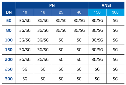
3G/SG: Cast Iron or Cast Steel (optional)
SG: Cast Steel
– Turbine wheel:
Standard: Delrin for DN 50 up to DN 200 for PN 10 / PN 16;
Aluminum alloy elsewhere.
Option: Aluminum alloy for DN 50 up to DN 200 for PN 10 /
PN 16
Approvals
EU type examination according to
• Measurement Instruments Directive MID 2014/32/EU as
per certificate No.: T11741 /T11742
• Pressure Equipment Directive PED 2014/68/EU as per
certificate No.: ISG-22-12-1978_Rev. F
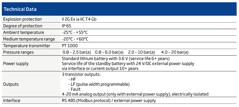
• Explosion Protection Directive ATEX 2014/34/EU as per
certificate No.: TÜV 17 ATEX 207566 X
Marking: II 2 G Ex ia IIC T4 Gb
• EMC-Directive 2014/30/EU as per
Test Report 1-5557/17-01-03_A
Recalibration Period (valid for Germany)
For TME 400 VMF:
As for mechanical Turbine Meters (8, 12 or 16 years,
depending on size und bearing design).
For TME 400 VCF:
For the measuring unit apply the same periods as for
mechanical Turbine Meters (8, 12 or 16 years, depending on
size und bearing design).
For the electronic totalizer including temperature and
pressure sensor the recalibration period of Electronic
Volume Correctors (EVCs) applies (i.e. 5 years).
Separate recalibration of measuring unit and totalizer is
acceptable.
MEASURING RANGE
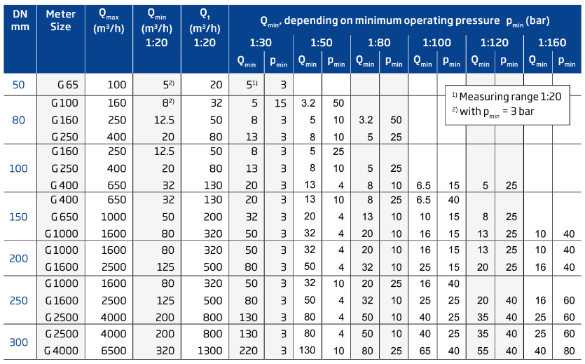
MEASURING RANGE

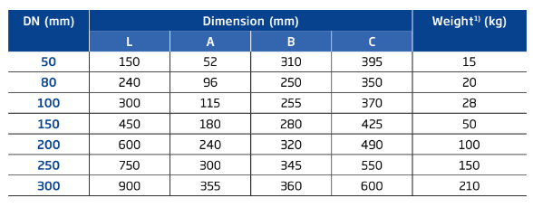
1) Approximate, valid for PN 10/PN16;
Weights will differ for other pressure
ratings.
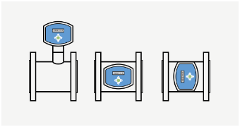
INSTALLATION OPTIONS, ARCHIVES, SOFTWARE
Options for Installing the Totalizer
With the TME 400-VMF the meter head can be mounted standing or
lying as well as rotated about the vertical axis.
For TME 400-VCF the meter head is mounted standing in any case due
to the pulse piping required.
For both the TME 400-VMF and the TME 400-VCF the remote totalizer
option for a separated mounting of the meter head in a distance of max.
10 m from the meter body is available.
Archives
Parameter changes, meter readings and events are
stored in the archives. For the TME 400-VFC additionally
measured values are stored.
The memory depth is in each case:
• Parameter archive (sealable) 300
• Parameter archive (free access) 300
• Event archive 200
• Periodic archive 9000
• Daily archive 100
• Monthly archive 25
The measuring period can be set to 15, 30 or 60 minutes.
Operating software RMGViewTME
The provided RMGViewTME software allows direct access to
the measuring electronics with a PC. The most important
functions are:
• Readout of all parameters
• Change of parameters
(with open calibration switch)
• Graphical display of measured values
• Creating test certificates and data sheets and their
output in pdf format
• Reading out the archives
• Export of parameters and archive data in Excel readable
format
The software is easy to use and all the data is displayed
systematically in clearly arranged tables. It is also possible
to combine selected measured values and parameters in
user-defined tables.